이득우의 게임 수학
렌더링은 그릴 물체의 정보를 GPU에 위임해 처리하도록 하는 것이 일반적이다.
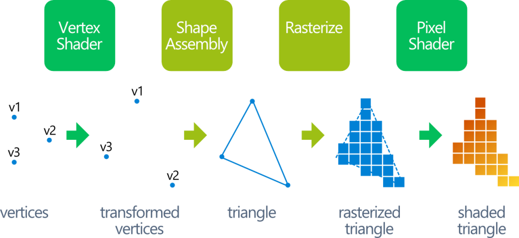
CPU 내부에 설정된 워크플로우를 렌더링 파이프라인(Rendering pipeline)이라고 한다.
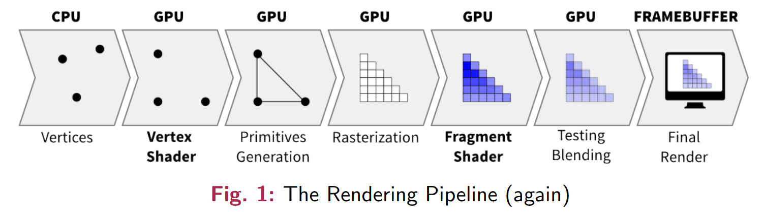
책의 예제인 CK소프트렌더러는 학습을 위해 4단계로 렌더링 파이프라인을 단순화시켜 구성했다.
- 정점 변환
게임 오브젝트에 연결된 메시의 모든 정점 정보를 정점 버퍼와 인덱스 버퍼에 직렬화하는 과정이다. - 정점 처리
직렬화된 모든 정점을 모델링 행렬을 통해 로컬 공간에서 월드 공간으로 변환하는 과정이다. - 픽셀화
메시를 구성하는 삼각형 폴리곤마다 픽셀화를 진행하는 과정이다.
무게 중심 좌표를 활용해 각 폴리곤에 속하는 픽셀들을 추려낸다. - 픽셀 처리
폴리곤을 구성하는 각 픽셀의 최종 색상을 구하는 과정이다.
텍스처로부터 UV 좌표에 대응되는 색을 가져온 후, 필요하면 조명 등의 효과를 적용해 최종 픽셀 색상을 결정한다.
1. 정점 변환 단계
- 원본 메시 정보에 모델링 행렬을 곱해버리면 메시를 공유하는 다른 게임 오브젝트에도 영향을 미치므로, 메시 정보는 원본 데이터를 복제해 사용한다.
- DrawMesh() 함수와 같이 렌더링 파이프라인을 시작하는 함수가 호출되는 상황을 드로콜(Drawcall)이 발생된다고 한다.
// 책의 예제인 CK소프트렌더러에 구현된 정점 변환 단계

// 1. 정점 변환 단계
void SoftRenderer::DrawMesh2D(const class DD::Mesh& InMesh, const Matrix3x3& InMatrix, const LinearColor& InColor)
{
    // 메시의 구조를 파악하기 위한 로컬 변수
    // 정점 개수
    size_t vertexCount = InMesh.GetVertices().size();
    // 인덱스 개수
    size_t indexCount = InMesh.GetIndices().size();
    // 삼각형 폴리곤 개수
    size_t triangleCount = indexCount / 3;

    // 메시 정보를 렌더러가 사용할 정점 버퍼와 인덱스 버퍼로 변환
    vector<Vertex2D> vertices(vertexCount);
    vector<size_t> indice(InMesh.GetIndices());
    for (size_t vi = 0; vi < vertexCount; ++vi)
    {
        // 원본 데이터를 복제해 사용한다.
        vertices[vi].Position = InMesh.GetVertices()[vi];

        if (InMesh.HasColor())
        {
            vertices[vi].Color = InMesh.GetColors()[vi];
        }

        if (InMesh.HasUV())
        {
            vertices[vi].UV = InMesh.GetUVs()[vi];
        }
    }

    // 2. 정점 처리 단계
    // 모델링 행렬을 곱해 로컬 공간을 월드 공간으로 변환한다.
    VertexShader2D(vertices, InMatrix);

    // 그리기모드 설정
    FillMode fm = FillMode::None;
    if (InMesh.HasColor())
    {
        fm |= FillMode::Color;
    }
    if (InMesh.HasUV())
    {
        fm |= FillMode::Texture;
    }

    // 메시를 삼각형으로 쪼개서 각각 그리기
    for (int ti = 0; ti < triangleCount; ++ti)
    {
        int bi0 = ti * 3, bi1 = ti * 3 + 1, bi2 = ti * 3 + 2;
        vector<Vertex2D> tvs = { vertices[indice[bi0]] , vertices[indice[bi1]] , vertices[indice[bi2]] };
        // 3. 픽셀화 단계
        DrawTriangle2D(tvs, InColor, fm);
    }
}
2. 정점 처리 단계
- GPU는 렌더링 파이프라인을 구성하는 대부분의 과정을 고정시키고 이를 특화된 HW에서 처리한다.
- 하지만 몇몇 중요한 과정은 개발자들이 설계한 로직을 실행하도록 함수를 제공하는데, 이를 셰이더(Shader)라고 한다.
- GPU의 정점 처리 단계에서 개발자들이 변환을 직접 설계하도록 제공하는 함수를 정점 셰이더(Vertex Shader)라고 한다.
// 책의 예제인 CK소프트렌더러에 구현된 정점 처리 단계

// 2. 정점 처리 단계
FORCEINLINE void VertexShader2D(vector<Vertex2D>& InVertices, const Matrix3x3& InMatrix)
{
	// 위치 값에 최종 모델링 행렬을 곱해 로컬 공간을 월드 공간으로 변환
	for (Vertex2D& v : InVertices)
	{
		v.Position = InMatrix * v.Position;
	}
}
3. 픽셀화 단계
- 메시의 인덱스 버퍼로부터 가져온 삼각형을 무게 중심 좌표를 활용해 각 폴리곤에 속하는 픽셀들을 추려내어 그린다.
// 책의 예제인 CK소프트렌더러에 구현된 픽셀화 단계
// 3. 픽셀화 단계
void SoftRenderer::DrawTriangle2D(vector<DD::Vertex2D>& InVertices, const LinearColor& InColor, FillMode InFillMode)
{
// 렌더링 로직에서 사용하는 모듈 내 주요 레퍼런스
auto& r = GetRenderer();
const GameEngine& g = Get2DGameEngine();
const Texture& texture = g.GetTexture(GameEngine::BaseTexture);
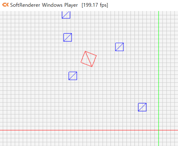
if (IsWireframeDrawing())
{
// 와이어프레임 모드로 메시를 그리기
LinearColor finalColor = _WireframeColor;
if (InColor != LinearColor::Error)
{
finalColor = InColor;
}
r.DrawLine(InVertices[0].Position, InVertices[1].Position, finalColor);
r.DrawLine(InVertices[0].Position, InVertices[2].Position, finalColor);
r.DrawLine(InVertices[1].Position, InVertices[2].Position, finalColor);
}
else
{
// 삼각형 칠하기
// 삼각형을 포함하는 가장 작은 직사각형 영역 설정
Vector2 minPos(Math::Min3(InVertices[0].Position.X, InVertices[1].Position.X, InVertices[2].Position.X), Math::Min3(InVertices[0].Position.Y, InVertices[1].Position.Y, InVertices[2].Position.Y));
Vector2 maxPos(Math::Max3(InVertices[0].Position.X, InVertices[1].Position.X, InVertices[2].Position.X), Math::Max3(InVertices[0].Position.Y, InVertices[1].Position.Y, InVertices[2].Position.Y));
// 무게 중심 좌표를 위해 점을 벡터로 변환
Vector2 u = InVertices[1].Position - InVertices[0].Position;
Vector2 v = InVertices[2].Position - InVertices[0].Position;
// 공통 분모 값 ( u·u * v·v - u·v * u·v )
float udotv = u.Dot(v);
float vdotv = v.Dot(v);
float udotu = u.Dot(u);
float denominator = udotv * udotv - vdotv * udotu;
// 퇴화 삼각형이면 그리기 생략
if (denominator == 0.f)
{
return;
}
float invDenominator = 1.f / denominator;
ScreenPoint lowerLeftPoint = ScreenPoint::ToScreenCoordinate(_ScreenSize, minPos);
ScreenPoint upperRightPoint = ScreenPoint::ToScreenCoordinate(_ScreenSize, maxPos);
// 두 점이 화면 밖을 벗어나는 경우 클리핑 처리
lowerLeftPoint.X = Math::Max(0, lowerLeftPoint.X);
lowerLeftPoint.Y = Math::Min(_ScreenSize.Y, lowerLeftPoint.Y);
upperRightPoint.X = Math::Min(_ScreenSize.X, upperRightPoint.X);
upperRightPoint.Y = Math::Max(0, upperRightPoint.Y);
// 삼각형 영역 내 모든 점을 확인해 영역에 속하는 점을 색칠
for (int x = lowerLeftPoint.X; x <= upperRightPoint.X; ++x)
{
for (int y = upperRightPoint.Y; y <= lowerLeftPoint.Y; ++y)
{
ScreenPoint fragment = ScreenPoint(x, y);
Vector2 pointToTest = fragment.ToCartesianCoordinate(_ScreenSize);
Vector2 w = pointToTest - InVertices[0].Position;
float wdotu = w.Dot(u);
float wdotv = w.Dot(v);
float s = (wdotv * udotv - wdotu * vdotv) * invDenominator;
float t = (wdotu * udotv - wdotv * udotu) * invDenominator;
float oneMinusST = 1.f - s - t;
if ( ((0.f <= s) && (s <= 1.f)) && ((0.f <= t) && (t <= 1.f)) && ((oneMinusST >= 0.f) && (oneMinusST <= 1.f)) )
{
Vector2 targetUV = InVertices[0].UV * oneMinusST + InVertices[1].UV * s + InVertices[2].UV * t;
// 4. 픽셀 처리 단계
r.DrawPoint(fragment, FragmentShader2D(texture.GetSample(targetUV), LinearColor::White));
}
}
}
}
}
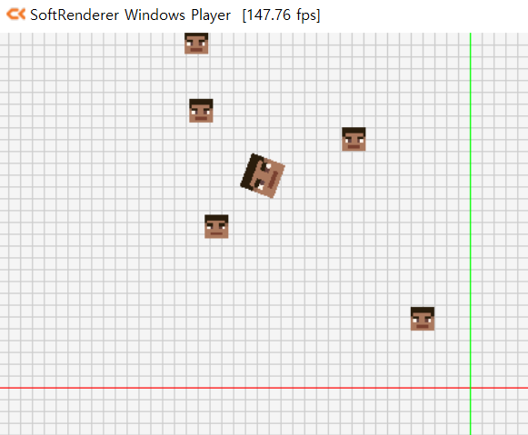
4. 픽셀 처리 단계
- 솎아진 삼각형 영역 점들의 최종 색상을 결정하는 과정이다.
- GPU에서 삼각형을 구성하는 픽셀을 파편(Fragment)이라고 하며, 개발자가 파편의 색상을 계산할 수 있도록 제공하는 함수를 파편 셰이더(Fragment shader) 또는 픽셀 셰이더(Pixel shader)라고 한다.
// 책의 예제인 CK소프트렌더러에 구현된 픽셀 처리 단계

// 4. 픽셀 처리 단계
FORCEINLINE LinearColor FragmentShader2D(LinearColor& InColor, const LinearColor& InColorParam)
{
	return InColor * InColorParam;
}
'게임 수학 > 이득우의 게임 수학' 카테고리의 다른 글
| 3차원 공간의 설계 (0) | 2023.05.04 |
|---|---|
| 카메라 시스템 (0) | 2023.05.03 |
| 게임 엔진의 워크플로우 (0) | 2023.05.01 |
| 리소스 저장소 (0) | 2023.04.30 |
| 로컬 공간과 로컬 축 (0) | 2023.04.29 |